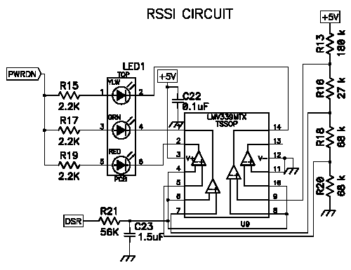
Digi XStream, XTend, and XBee modules now feature an ''analog'' output of the received signal strength relative to the receiver sensitivity of the module. This output is available as a PWM (pulse width modulation) signal on the config pin of the module (XStream pin 9, XTend pin 11, XBee pin 6)
The ATRP command is used to configure the duration of a PWM output on the config pin (pin 9 of the OEM RF Module) after last received packet. The PWM output is a 120Hz square wave where duty cycle varies to encodes fade margin (RX level relative to RX sensitivity). eg, 10% duty cycle = 10 dB fade margin (signal level of -100 dBm @ 9600 bps, -94 dBm @ 115 bps).
The schematic below shows a low pass filter than converts the PWM signal (labeled as ''DSR'' in the schematic) to an analog voltage and a comparator that will iluminate one of three LEDs depending on the signal strength.

The above RSSI circuit is for the XStream product line. For RSSI circuits for other Digi products, please refer to the interface board schematics for that particular radio. Interface Board Schematics.
Last updated:
Aug 23, 2017